
The purpose of this document is to describe the rules that apply to the generalization and editing of road networks and features in the Samgöngunet (Icelandic Road DataBase - IRDB) based on the current data product specifications.
The guide is linked to the sub-process of Information Management about assets and their location within the main process of Collecting and Processing Information about roads and railways.
The document covers the regulations to be used when editing the IRDB's road network and features. Editing refers to the work carried out in systems synchronized with the IRDB.
This section lists the definitions of key terms used in the document.
Náttúrufræðistofnun has the responsability to build the backbone of the system and maintain the system working. Vegagerðin owns the project and is responsible for the data correctness and
The road network in IRDB is a simplification of the real physical road network. To be able to make this simplification, rules are required to create a consistent road network. These rules are called Generalization Rules and should guide the work of creating the road network in IRDB.
There are three basic general rules:
Furthermore, it is required that:
This section describes the generalization rules that apply to the road network.
The reference line should represent the centerline of the roadway.
Lateral variation of the reference line should be minimized. Temporary widenings, such as parking spaces, bus stops, or overtaking lanes, should not be considered.
| Type of Road | Placement of the center line |
|---|---|
| “Regular” road and street | Center of the roadway.
|
| Physically separated roadways between two intersections | Center of the roadway, one line per direction. 
|
| Roadways that are physically separated by more than 200 m | Center of the roadway, one line per direction.
|
| Divided multi-lane road of the 2+1 type | Centerline of the outer lane. One line per direction. |
| Divided multi-lane road of the 2+2 type | Center of the roadway, one line per direction. |
| Multi-lane road, e.g., 4-lane road | Center of the roadway. If physically separated roadways - one line for each direction. |
| Motorway, expressway | Center of the roadway in each direction. The line does not always coincide with the painted lane line. |
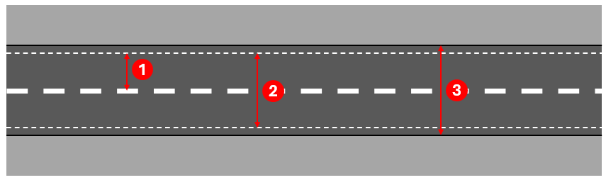
To know where the line should be placed, it is important to understand the concepts of lane, roadway, and carriageway. These are described in the Figure 2 below.
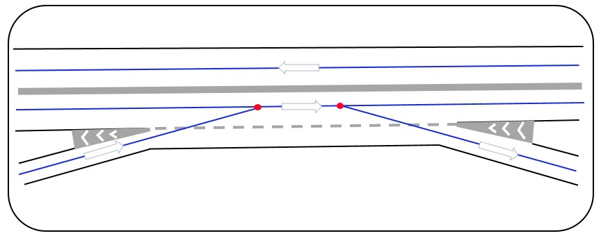
A deviation from the standard procedure applies to the placement of reference lines on a road section that has two lanes in one direction throughout its entire length and alternating one and two lanes in the other direction. In other words, a combination of a 2+2 and 2+1 road. To avoid the reference line oscillating in and out, it should be placed according to Figure 3 below, where the left lane is maintained.
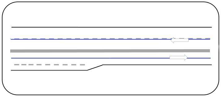
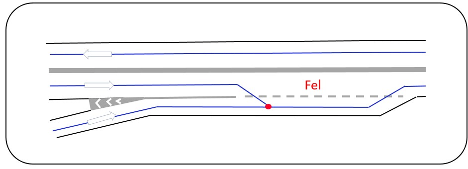
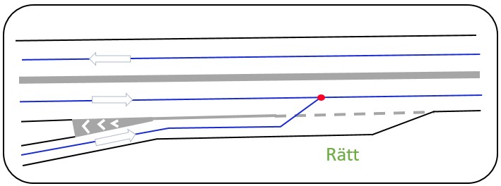
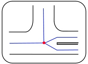
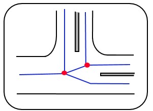
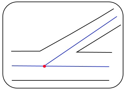
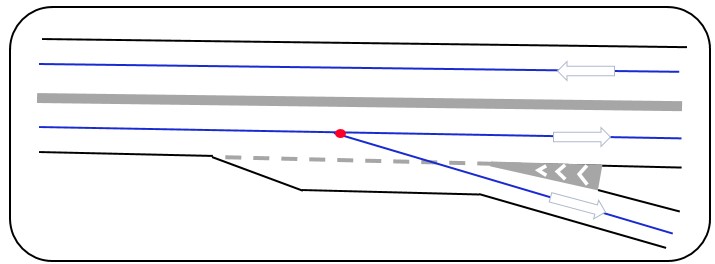
Another case of deviation handling is if the right lane is a long entry ramp. In this case, the reference line should continue in the left lane, and not angle into the right lane, see Figure 4 and Figure 5.
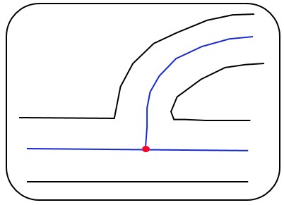
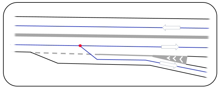
It is quite common for 2+1 roads at interchanges to switch from 1 lane to 2 lanes. In such cases, the reference line should also angle out to the outer lane. See the figure below. Figure 6 where the entry ramp ends and there are two lanes.

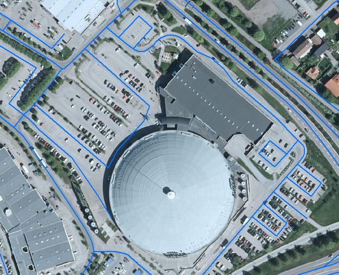
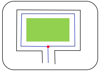
Deviation handling may be necessary for open areas where there are designated paths, such as parking spaces in a parking lot. In these cases, it is allowed to register reference links in the open area. See the figure below. Figure 7 for an example of a road network in a parking area at a shopping center.
The continuity rule for road networks means that the road network should avoid switching back and forth between one and two reference lines due to short breaks in the median barrier or intersections. When representing a road section with separate roadways, repeated switches between two separate reference lines and a single reference line should be avoided where link lengths are less than 200 meters. This is called the continuity rule. When determining the length of physical separation (e.g., a median or barrier), any interruptions in the form of connecting roads should not be considered.
Figure 8: Two separate reference lines are created for the entire stretch between nodes A and B because the break in the physical separation is less than 200 meters.

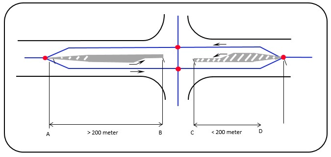
Figure 9: If any of the sections from A to B or C to D is longer than 200 meters, two separate reference lines are created for the entire stretch from A to D.
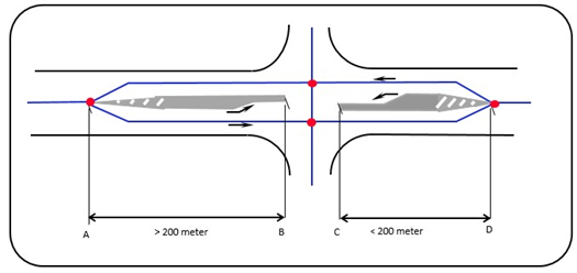
Figure 10: To maintain continuity, a painted no-passing zone can also give rise to separate roadways.
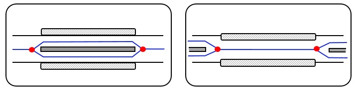
The limitation of 200 meters does not apply to bridges according to the continuity rules. A bridge should always be represented as it appears, regardless of its length. If there are separate roadways on the bridge with a physical barrier between them, it should be represented with two reference links. However, if there is only one roadway, it should be represented with a single reference link.
Figure 11: A bridge is always represented as it appears, regardless of its length. The continuity rule does not apply to bridges.
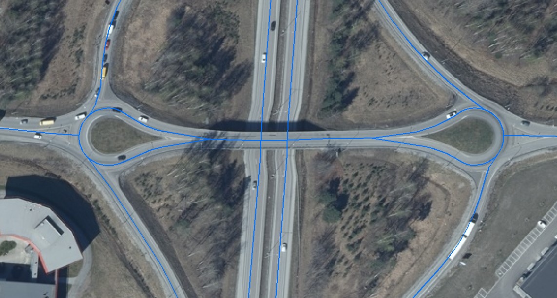
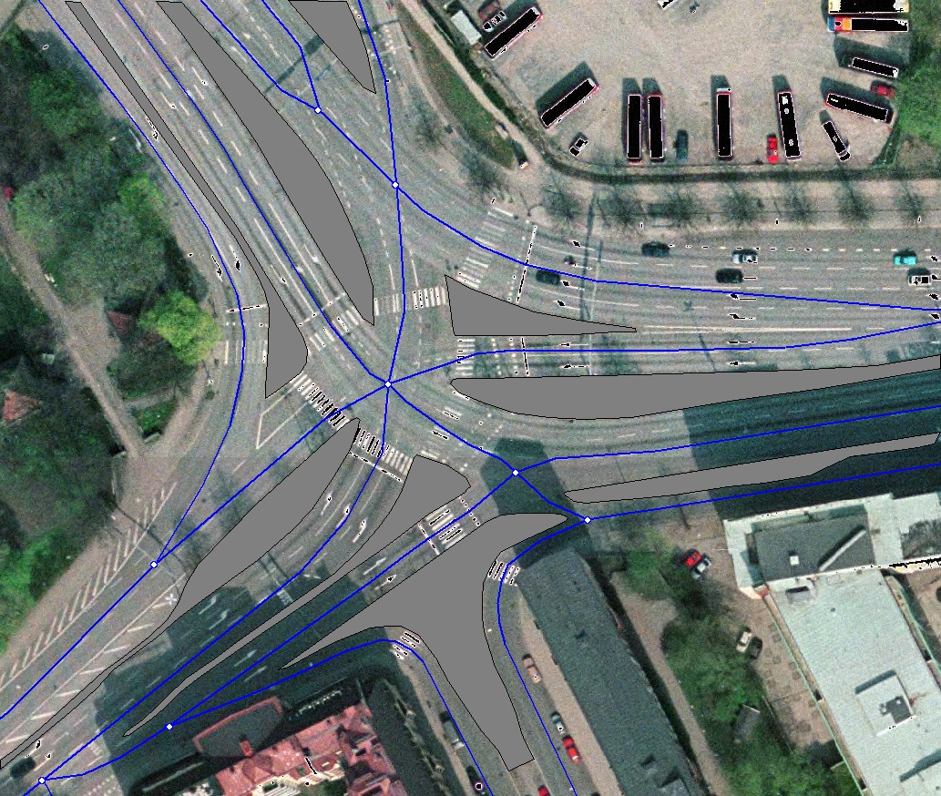
The figure below shows a construction where the roadways are physically separated by medians from the roundabout to the T-junction on the right side of the figure. To the right of the T-junction, there is a painted traffic separator.
Figure 12: Example of the continuity rule.
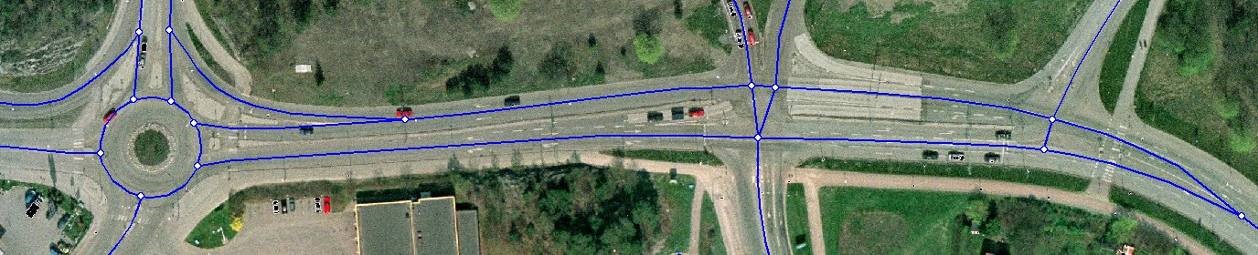
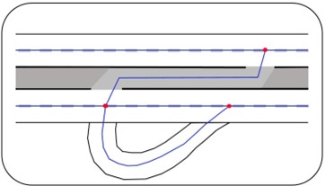
To maintain continuity, the reference links should converge into a node only after the median at the traffic separators near the pedestrian crossing on the far right.
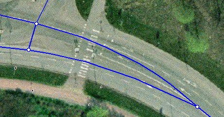
Figure 13: Detail from the figure above showing the eastern part.
Nodes should only be placed within the road network:
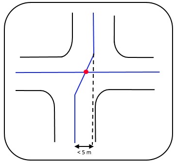
The basic rule for the distance between nodes is that the distance should exceed 5 meters. Nodes should be placed so that the length (link length in the xy-plane) between two nodes exceeds 5 meters. This may result in the links being merged into a single node if the distance is less than 5 meters.
An exception applies to intersections with the pedestrian and bicycle network, where a distance down to 2 meters is acceptable. It is never allowed to place nodes closer than 2 meters.
Figure 14: Node placement for short links.
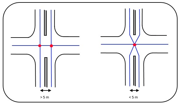
The short links created when constructing node locations should exceed 5 meters to generate multiple nodes. If the distance is less than 5 meters, the intersection is constructed with a single node.
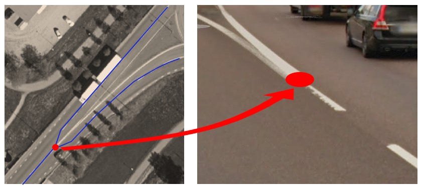
At channelizations, nodes should be placed where the painted separator (spärrfält) begins or ends.
Figure 15: Node placement at channelization.
Where two roadways represented by two separate reference lines merge into a single roadway, the basic rule is that the node is placed where the painted separator (spärrfält) ends.
Figure 16: The node is placed where the painted separator starts/ends.

A node should be placed where a road begins or ends. This can look very different in various cases, but the following examples can provide guidance.
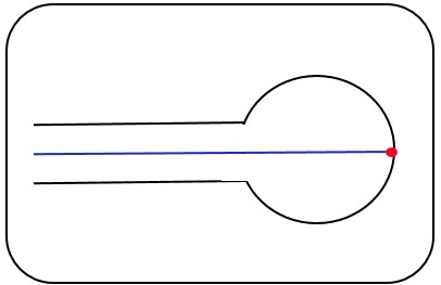
Where a road ends in a turning area or another large open space, the node is placed at the intersection between the reference line and the far edge of the drivable surface.
Figure 17: Road end in a turning area.
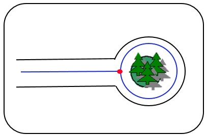
Where a road ends in a turning loop with a physical barrier in the center of the loop, the reference line should represent the actual position of the turning loop.
Figure 18: Road end in a turning loop.
For traffic intersections, crossings, or roundabouts, the basic rule described in Chapter 5.1 General for road, bicycle, and pedestrian networks should apply. Additionally, assessments must be made in each individual case to determine how nodes should be placed. The generalization rules described in the following sections only cover the fundamental situations explicitly.
If uncertainties arise regarding how depictions should be made, the following priority order applies:
When a new road is added to an intersection, the entire intersection must be reconsidered as a whole before determining where the nodes should be placed.
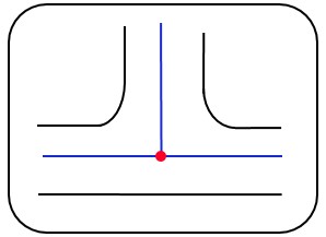
The node in a T-junction is placed at the intersection of the reference lines.
Figure 19: Simple T-Junction.
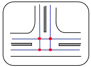
If all incoming roads have separate roadways, the basic rule provides for four nodes, provided that the link lengths do not fall below 5 meters.
Figure 20: All roads have separate roadways.
If one incoming road has separate roadways, the basic rule provides for one node.
Figure 21: One road with separate roadways and two without.
If two incoming roads have separate roadways, the basic rule provides for two nodes.
Figure 22: Two roads with separate roadways and one without.
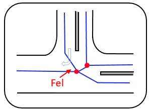
In this type of intersection, it is important to avoid sharp angles if possible. The figure below illustrates an incorrectly generalized intersection that could create problems when navigating from north to west.
Figure 23: Incorrectly generalized intersection with a sharp angle.
When a depiction involves a loop, it should always be generalized with two separate reference lines: one reference line representing the loop and another reference line representing the road to the connecting loop, with a node used for the connection.
Figure 24: T-Junction with a loop.
The reference lines should reflect how the junction is constructed. The basic rule also applies in skewed T-junctions, where nodes are placed at the intersection of the reference lines.
Figure 25: Skewed T-Junction.
In most cases, the road connects perpendicularly, and in such cases, the node should be placed as shown in the figure below.
Figure 26: Skewed T-Junction with perpendicular connection.
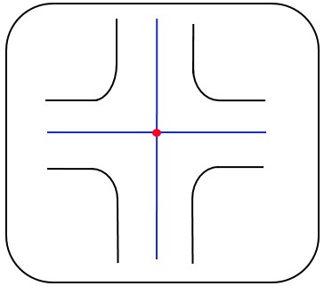
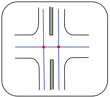
In a four-way junction, the node is placed according to the basic rule at the intersection of the reference lines.
Figure 27: Simple Four-Way Junction.
If all incoming roads have separate roadways, the basic rule provides for four nodes, provided that the link lengths do not fall below 5 meters.
Figure 28: All incoming roads have separate roadways.

Figure 29: Three roads with separate roadways and one without.
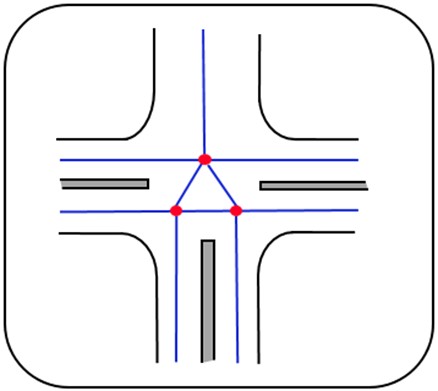
Figure 30: Two roads with separate roadways and two without. In these situations, it can be challenging to avoid sharp angles.
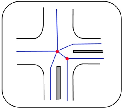
Figure 31: Two roads with separate roadways and two without.
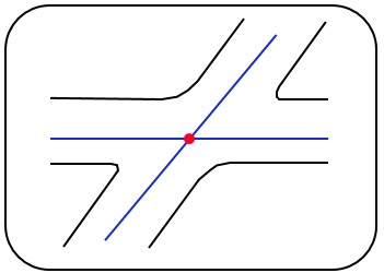
In skewed four-way junctions, the node is placed at the intersection of the reference lines.
Figure 32: Skewed Four-Way Junction.
A staggered four-way junction gets one node if the distance between nodes at the intersection of the reference lines is less than 5 meters.
Figure 33: Staggered Four-Way Junction with two nodes.
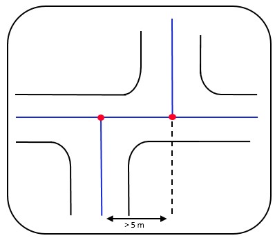
Figure 34: Staggered Four-Way Junction with one node.
When a new road is added to an intersection, the entire intersection must be reconsidered as a whole before determining where the nodes should be placed.
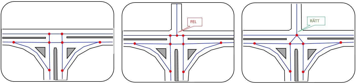
In the case below, a new road has been connected to an existing junction. In the incorrect example, the entire junction's generalization has not been taken into account, but instead, the new road was merely connected. The figure below shows the correct generalization.
Figure 35: Original junction, incorrectly connected new road, and correctly connected new road.
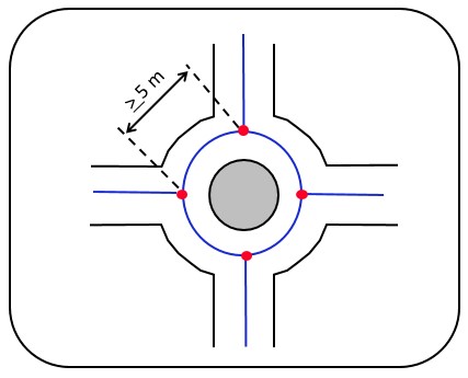
Roundabouts are depicted as they are designed, usually as a circle. Nodes are placed where the reference lines of the connecting roads intersect the roundabout's reference line. Small roundabouts without channelization that are fully drivable and where a node distance of at least 5 meters cannot be achieved are always generalized into a single node.
Figure 36: Roundabout (5 m applies for the distance between nodes).
If channelizations are present at a roundabout, they are handled according to Chapter 5.2.6.12 Channelizations in Intersections.
At so-called “drops,” the node is placed where the hatched area or median begins or ends.
Figure 37: Drop-Type Intersection.
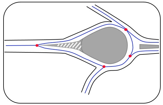
Figure 38: Example of a “drop.”
If a physical barrier exists, the reference lines should not converge into a single node at the end of the drop but should continue with two reference lines according to the basic rule for depicting the road network.
Figure 39: Drop with a physical barrier.
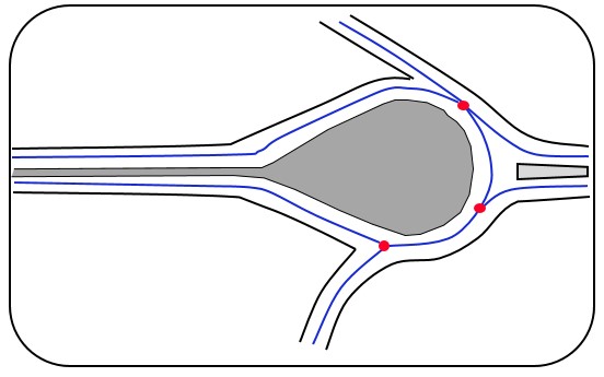
Figure 40: Example of a drop with a physical barrier.
The basic rule is that off- and on-ramps should always connect to the primary road immediately after the hatched area or ramp nose's hatched area if no hatched line exists.
The following scenarios for connections are exemplified:
Figure 41: On-Ramp.
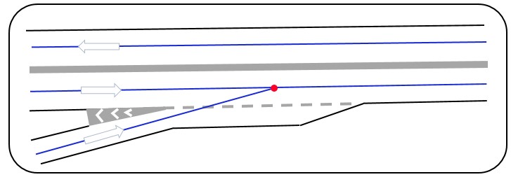
Figure 42: Off-Ramp.
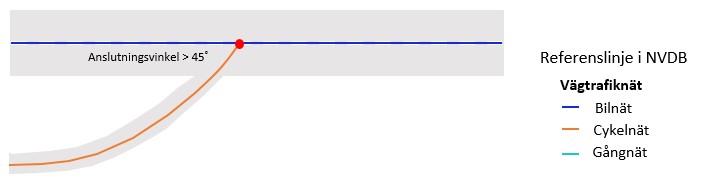
Or if this is not possible, an angle should be made towards the primary road without crossing the median, hatched area, or hatched line, typically at about a 45-degree angle.
Figure 43: On-Ramp.
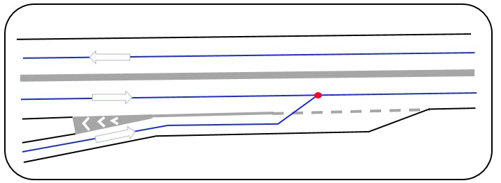
Figure 44: Off-Ramp.
Simultaneous on- and off-ramps (weaving lanes) should not be depicted with their own link but should follow the basic rule. If the distance between nodes is less than 5 meters, a single node is created in accordance with the basic rule.
Figure 45: Weaving Lanes.
Channelizations in the form of medians or marked hatched areas lead to the separation of links according to the following rules:
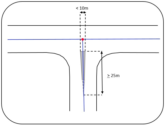
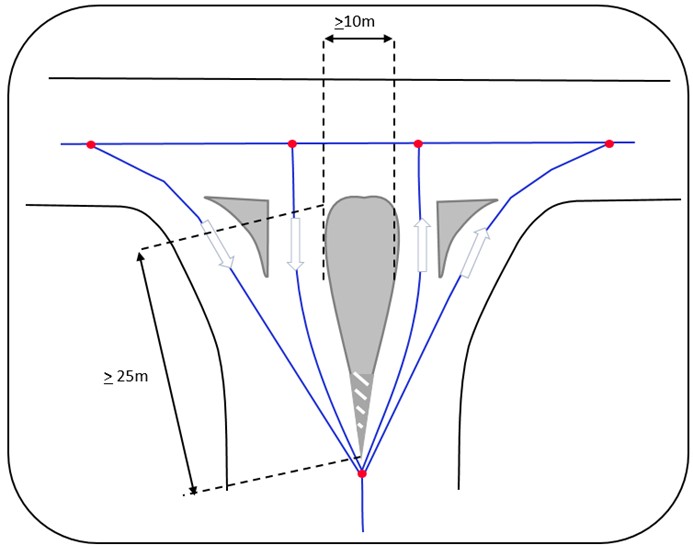
1. For medians that separate traffic with opposite directions, known as central medians, one side of the channelization must be at least 25 meters long and the shortest side at least 10 meters long. Consideration should, in most cases, only be given to permanent physical obstacles and barriers. Painted hatched areas can also result in the separation of links if it is necessary to associate information with a specific traffic movement or describe the functionality of the road network at the location. Hatched areas that meet the length and width measurements of 25 meters and 10 meters respectively, and are also marked with permanent physical barriers such as road signs or markers, should always be depicted with separate lines.
Figure 46: One side of the median is longer than 25 meters, the shortest side is longer than 10 meters. The median separates traffic in opposite directions.
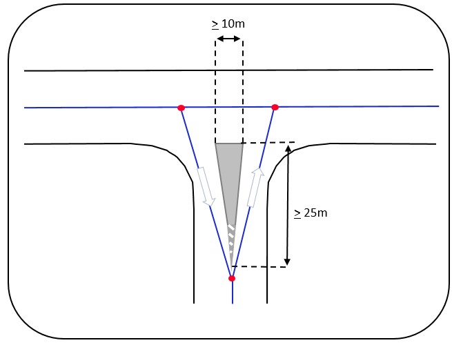
Figure 47: One side of the median is longer than 25 meters, the shortest side is shorter than 10 meters. The median separates traffic in opposite directions.
2. Medians that separate traffic moving in the same direction, so-called directional medians, should result in separate links. See the figures below.
Figure 48: Directional medians.
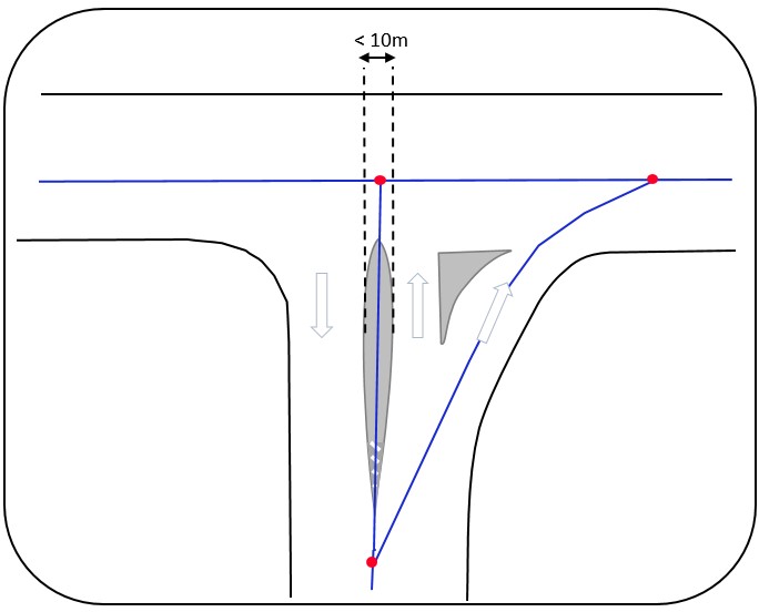
Figure 49: Directional medians.
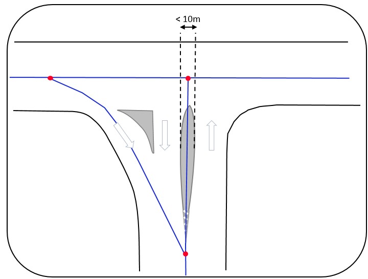
Figure 50: Directional median creates separate links to the left and right. Central median too narrow to divide the link.
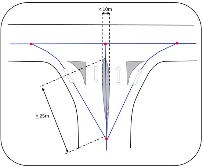
Figure 51: All medians in the intersection meet the requirement for the separation of links.
To enable the connection of traffic regulations or infrastructure data to the correct reference line, painted hatched areas that separate traffic in the same direction should also result in separate links.
Figure 52: Painted directional channelization. The traffic rule "Yield" applies to the right traffic movement, leading to the creation of a separate link for it.
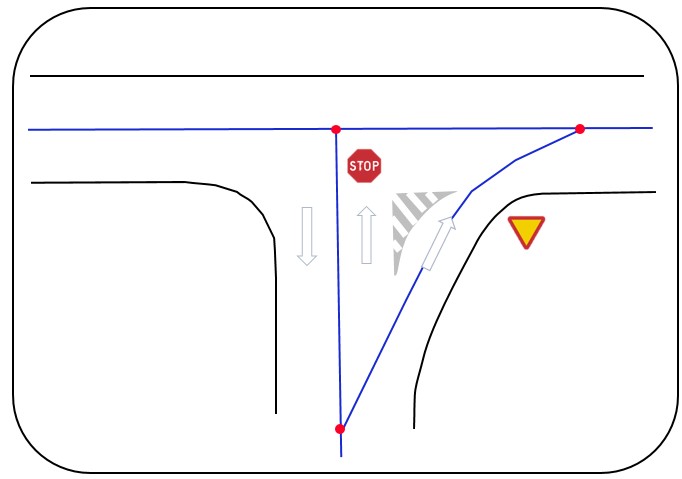
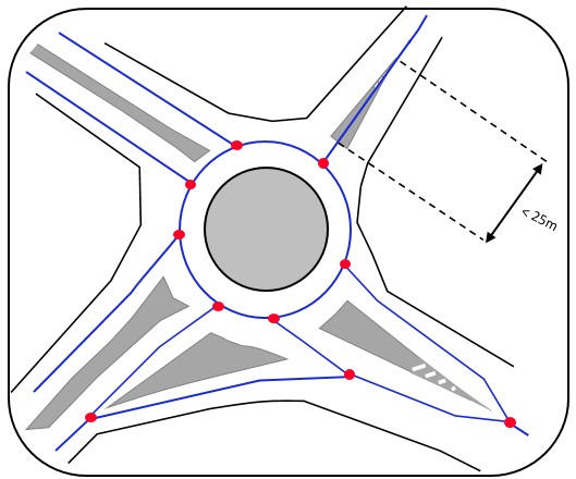
Figure 53: Roundabout with different types of channelizations.
Topology takes precedence over geometry. A simple and topologically correct depiction should be prioritized over a geometrically accurate depiction. This is particularly important in intersections where roads with separate carriageways meet. To achieve a simple and correct depiction of the topology, without unnecessary nodes and links, the requirements for geometric shape and sometimes even positional accuracy are often disregarded within the intersection area. Otherwise, there is a risk of unacceptable variations in the depiction of the road network depending on who creates the network if geometric accuracy is prioritized.
In complicated intersections, there can be many reference links that meet. It is then essential to first ensure that all topological connections are depicted correctly, i.e., that all connectivity options are represented. A suitable workflow can be as follows:
Figure 54: Example of a complicated intersection.
At turnaround points where the central reservation is not blocked with a barrier or other obstacle, a cross-link should always be added.
Figure 55: Two different types of turnaround points where cross-links should be added.

The cross-link must be adapted to the vehicle movement at the location. Below is an example where barriers block parts of the area between the roadways.
Figure 56: Example of a turnaround point where the link between roadways must be adapted to vehicle movement.
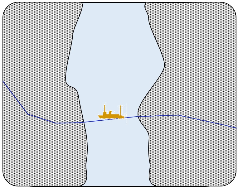
The geometry of the ferry route should be depicted as a line between the landings. The line should follow the likely route of the ferry. Figure 57.
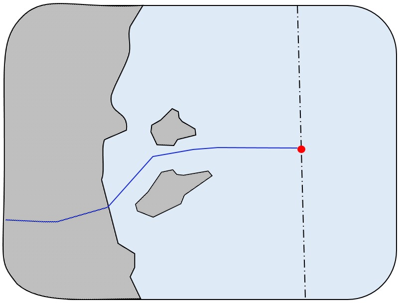
Ferry routes to foreign countries are depicted similarly but with a node placed on open water. The node is positioned at the territorial boundary in the direction of the destination. Figure 58.
This section describes the generalization rules that apply to both pedestrian and bicycle networks, where the data product 'Road Traffic Network' has the value pedestrian network or bicycle network. The generalization rules should guide the work of creating the pedestrian and bicycle network in the IRDB.
The basic rule is that the reference line should depict the centerline of the bicycle lane or sidewalk, or the centerline of the bicycle lane segment. Figure 59.
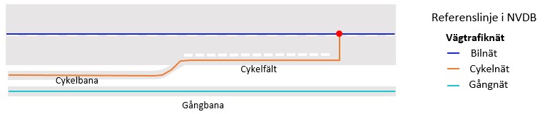
The illustrations below describe various typical cases where the reference line for pedestrian and bicycle networks should be registered. A guideline can be the traffic signs for pedestrian and bicycle networks. Figure 60.
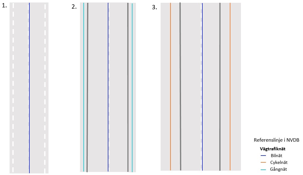
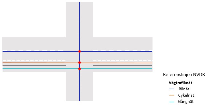
1. A road without a designated area for pedestrians and cyclists – no reference line for the pedestrian or bicycle network in IRDB.
2. A road with sidewalks along it – a reference line for the pedestrian network in IRDB (one reference line for each side in this case).
3. A road with a shared lane for pedestrians and cyclists along it – a reference line for the bicycle network in IRDB (one reference line for each side in this case).
Figure 61.
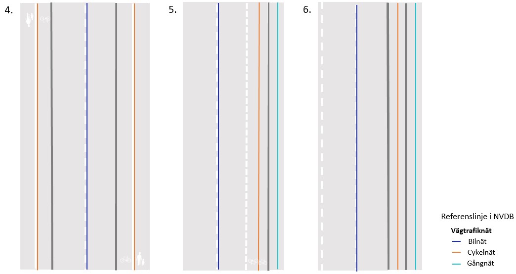
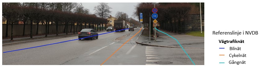
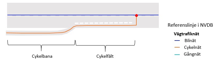
4. A road with a lane for pedestrians and cyclists that is divided by road markings, separators, or similar into a part for pedestrians and a part for cyclists – reference line for the bicycle network in IRDB.
5. A road with a lane for pedestrians and markings for bicycle lanes on the road – a reference line for both the bicycle and pedestrian networks in IRDB.
6. A road with a lane for pedestrians and cyclists separated by a physical divider – a reference line for both the bicycle and pedestrian networks in IRDB. (Refuges should not lead to separation of the pedestrian and bicycle network). Figure 62.
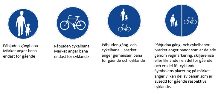
Figure 63 provides examples of typical cases 4 and 5 as listed above.
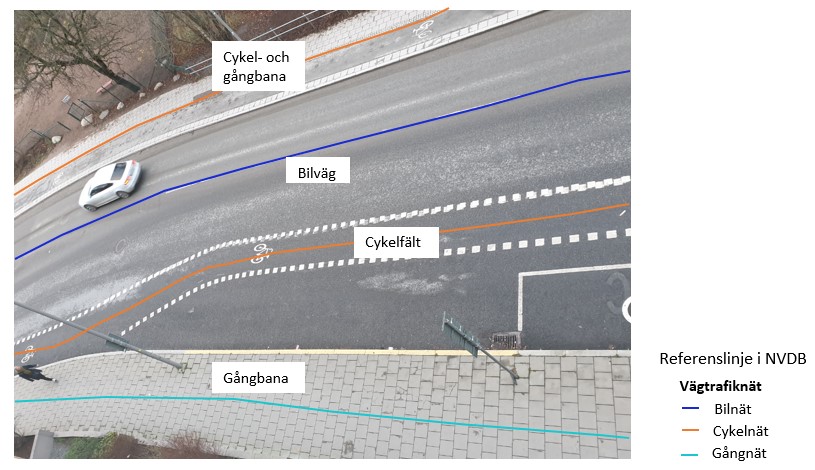
Figure 64 provides an example where a pedestrian and bicycle path should be divided into two separate reference lines due to a physical divider (typical case 6).
The lateral variation of the reference line should be minimized. Therefore, temporary widenings of pedestrian and bicycle paths or bicycle lanes should not be considered. When pedestrian and bicycle networks share the same area but differ significantly in construction, color, and/or material for each type of traffic, they should be represented with separate reference lines.
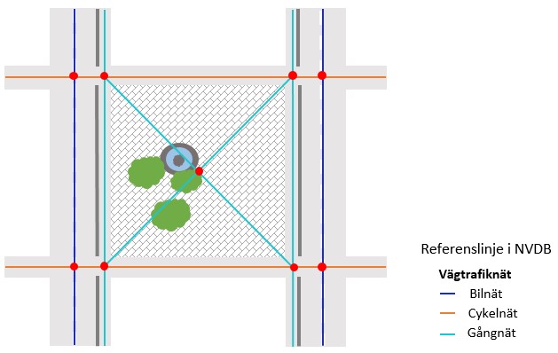
Pedestrian and bicycle paths in open areas such as squares, parking lots, and shared traffic zones should be represented with one or more reference lines that show the main routes taken by users across the area. If the networks cross each other, they should be connected with a node. Figure 65.
The geometry lines for sidewalks, bicycle lanes, and bicycle paths should not cross the road network back and forth due to one of the lines having lower accuracy during digitalization than the other. It is also essential to ensure that the pedestrian and bicycle networks remain on the correct side of the road network’s line. The distance between the networks, when they run parallel, should have a reasonable relation to the road width of each geometry line.
The geometry for the vertical section that an elevator represents cannot be handled in IRDB. Therefore, it is necessary to compromise on accurate geometric representation and let the section slope slightly so that the plane coordinates at the lower and upper positions of the elevator are approximately one meter apart.
Pedestrian crossings and bicycle passages that run next to each other should have a common reference line. Figure 66.
In complex intersections, it may be necessary to prioritize topological simplicity over positional accuracy and form. This means that, in order to have as few nodes as possible in the intersection, the reference line in the intersection area may deviate from the intended roadway or bicycle lane that it should depict.
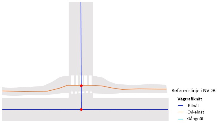
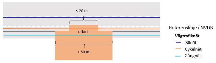
Continuity is sought for the reference line. This means, for example, that a bicycle lane or sidewalk that temporarily ends at an intersection should still be represented continuously through the intersection, past a bus stop, or over a driveway. The same applies to sidewalks where the pedestrian network continues over the intersection, even in the absence of a marked crosswalk. Figure 67.
According to the continuity rule, the bicycle lane continues over the driveway even though the bicycle lane markings temporarily disappear. The same applies to sidewalks, where the pedestrian network continues over the driveway even when the sidewalk is missing. Bicycle paths and bicycle lanes are depicted with a continuous line if they reappear within 20 meters. Sidewalks and pedestrian paths are depicted with a continuous line if they reappear within 50 meters. Figure 68.
Just like in the road network, nodes should only be placed at the following locations within the pedestrian and bicycle networks:
The difference is that nodes are placed so that the length (in the xy-plane) between two nodes does not fall below 2 meters. An exception exists for elevators where 1 meter is acceptable. This may lead to links sometimes being merged into a single node. In the road network, the distance should not fall below 5 meters. Figure 69.
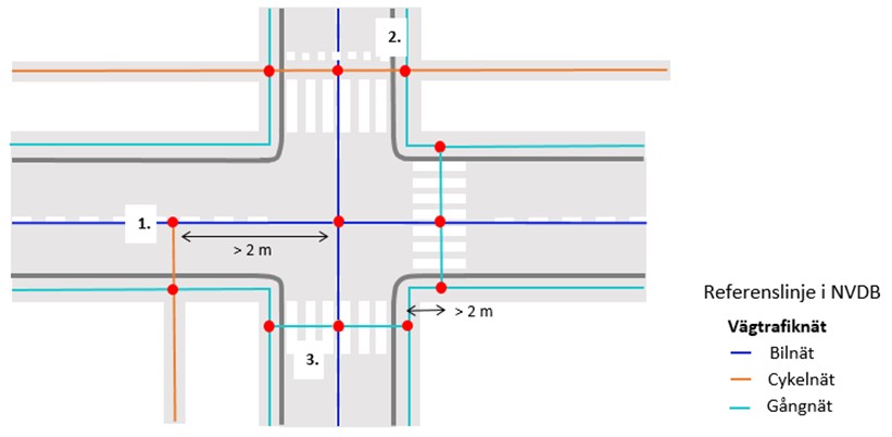
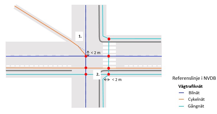
1. The figure above shows how a bicycle path connects to the road network when the distance from the perpendicular connection is greater than 2 meters to the nearest node in the road network. If the connection of a pedestrian or bicycle network occurs within 2 meters from an existing node in an existing network, the connection should instead be made to the existing node.
2. The figure also shows how a crosswalk with an adjacent bicycle passage connects to sidewalks and the road network with nodes.
3. At-grade intersections between pedestrian, bicycle, and road networks should be marked with nodes. The figure shows how sidewalks connect with nodes to the bicycle and road networks.
Figure 70.
This chapter illustrates the basic rules for how pedestrian and bicycle networks should be connected to the road network. It is also essential to connect the pedestrian and bicycle network to the road network at points where users might choose to continue their journey on the road network, even though the pedestrian and bicycle network does not technically connect to the road network but runs parallel to it. Figure 71.
Pedestrian and bicycle networks should always be connected to the road network at turning areas. If the link is shorter than 2 meters, the networks should be merged into the same node. This can be done in three ways:
Each address point should be able to be projected orthogonally and have free passage to some part of the road network at a maximum distance of 5 meters. Figure 74.
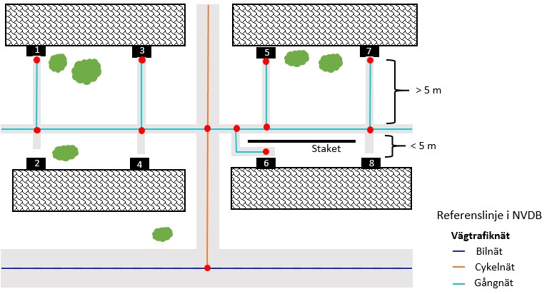
Address points 1, 3, 5, and 7 should have a reference line from the continuous walkway to the door (the address point) because the distance out to the walkway is greater than 5 meters. Address points 2, 4, and 8 should not have a reference line from the continuous walkway to the door (the address point) because the distance out to the walkway is less than 5 meters. Address point 6 should have a reference line from the continuous walkway to the door (the address point) because a fence prevents free passage directly to the walkway, resulting in a detour longer than 5 meters.
If road, pedestrian, and bicycle networks are not connected, route planning can become very confusing for cyclists and pedestrians, potentially leading them to take several kilometers of detours just to reach the other side of the street.
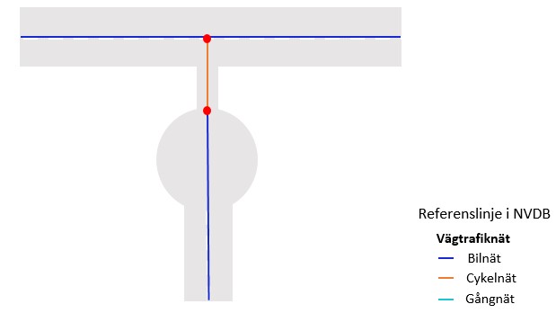
To facilitate route planning for cyclists and pedestrians, it is crucial to connect the road network with the pedestrian and bicycle network where appropriate. There should always be a node when reference lines for pedestrian, bicycle, and road networks cross at grade, allowing cyclists and pedestrians access to the road network. If access is not permitted for one or more types of vehicles or road users, appropriately chosen features should prevent passage.
It is also essential to connect the pedestrian and bicycle network to the road network at points where users might choose to continue their journey on the road network, even if the pedestrian and bicycle path does not technically connect to the road network but runs parallel to it. Otherwise, route planning for cyclists and pedestrians becomes unreasonable.
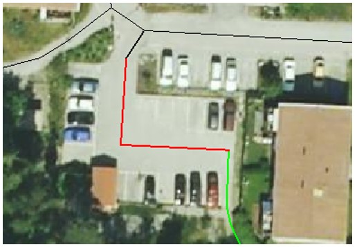
During the digitalization of pedestrian and bicycle networks, it is sometimes necessary to include certain roads that are not mandatory for the road network but become necessary to achieve a navigable pedestrian and bicycle network. These are, in most cases, small private roads and parking areas. For example, a parking lot that has not yet been registered in the road network may be needed to allow access from the connecting pedestrian and bicycle path to the street. A navigator can only follow roads with registered reference lines and make decisions at nodes but does not recognize connections that exist in reality if the digital equivalent is missing in the database. Figure 75.
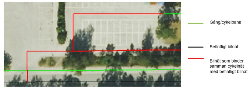
Roads within parking areas are part of the road network and must be present to connect the pedestrian and bicycle network with the rest of the network. Figure 76.
A rural road is a design type aimed at improving the conditions for unprotected road users. The term "Bygdeväg" is used synonymously with "Bymiljöväg," especially in municipal planning. The design may vary, but the basic idea is that the road is narrowed using painted edge lines. Figure 77.
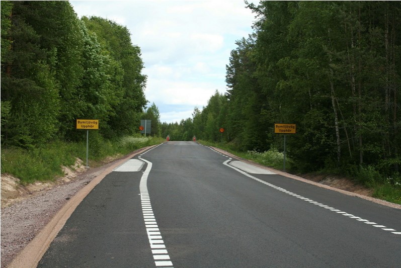
For the time being, no form of pedestrian and bicycle path is registered where there is a rural road. Since vehicles are allowed to drive on the sides of the road, it is not considered a pedestrian and bicycle path, bicycle lane, or bicycle path according to the definition used so far.
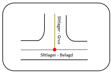
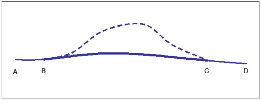
A feature that fully covers a section should always be described from node to node. The extent should be drawn all the way to the node to avoid creating gaps. In the example below, the wearing course should be defined with the value gravel all the way to the paved section. See Figure 78 below.
This section covers editing the road network. Different approaches to editing the road network are presented in the following sections.
When new objects are created in the IRDB, it is fundamentally because the reality has changed. A new object has been added and must also be registered in IRDB. A new object can be a new reference link or a new node.
When an object in the IRDB is corrected, it is done for one of the following reasons:
Corrections are typically definitive and cannot be restored after being carried out. A correction does not create a "before and after" record, as there is no history created.
A reference link has a topology, which includes information on the nodes it connects to. The reference link also has a geometry that describes its shape. Every reference link has a geometry that also determines its length.
When reality changes, the corresponding object in the IRDB must also change. A change creates a history by saving how it looked before and after the change in the database. In contrast, corrections do not save history.
Examples of road network changes:
In all of the examples above, you can see how it was before the change and how it turned out after the change by using different observation dates.
When objects cease to exist or are no longer valid in reality, they can also be terminated in the IRDB. The action is fundamentally a change and is carried out by setting an end date for the object. By using an observation date before the closure, you can see the object as it looked then. After the end date, the object is no longer visible. Therefore, closure creates a history.
The objects that can be closed in the IRDB are a part of a reference link or an entire reference link. Essentially, it is the parts of reference links that are closed. When all parts of a reference link are closed, the reference link is indirectly closed.
When closing a road network that has a road number, the feature "Road Number" must also be closed. The road number is a contiguous feature, with an exception for access roads that do not connect to a state road. In other words, road numbers should not be present on access roads that do not connect to a state road.
When making geometric corrections, do not close the old section and create a new, more accurate one parallel to the old one. This is a common mistake that must be avoided at all costs. Think of it this way: When viewing the corrected road, you do not want to see the old, incorrect geometry before a certain date. By performing a correction instead of a closure, it will be accurate.
Removal means that an object will no longer exist in the IRDB. It cannot even be viewed historically. Therefore, removal must be applied with the utmost caution. Road network segments, in principle, should not be removed except for obvious errors, such as when a railway is mistakenly registered instead of a road. IRDB experts must always be consulted. Generally, road network segments should instead be closed. Removal is fundamentally a correction and does not leave a history behind.
A reference link may only be removed if it is clear that it should never have existed at any stage. An example of such a situation is a road segment that mistakenly exists in the database but has never existed in reality.
The objects that can technically be removed in the IRDB are:
Reference links should have a direction, but there is no requirement that they be registered in a specific direction. In the IRDB, there is a preference to primarily store reference links based on the intended direction of travel, such as the intended direction for on and off-ramps. For dead-end roads, the direction of the link goes from the intersection to the end of the road.
Secondly, the directions of reference links should follow the directions of road numbers or street names. If none of these guidelines are available, the directions of the reference links should run from south to north and west to east.
Never change the direction of existing reference links.
Consultation between road managers should always take place when changes in one road manager's network affect another road manager's network, such as when a node at the connection between networks is affected or when a feature's extent crosses a municipal boundary. The consultation should be documented when delivering data to the IRDB.
For detailed descriptions of attributes, structure, quality requirements, and rules for collecting data for each feature type, see the respective Data Product Specification (DPS). Information on approved attribute values for features can be found directly in the data product specifications or through Lastkajen, which is the Swedish Transport Administration's service for an overview of all features. A user account for Lastkajen is required. To access the attributes of a specific feature with associated coding in the list, select "Show Data Catalog."
When new features are created in the IRDB, it is fundamentally because reality has changed. A new feature has been introduced and must be registered in the IRDB.
When an object in the IRDB is corrected, it is due to errors in the object. Example: A feature has one or more incorrect attribute values. A typical characteristic of a correction is that there is no time interval showing "before and after." A correction does not provide an image of the object at one specific date and a different one at another date, i.e., no history is created.
When reality changes, the corresponding object in the IRDB should also change. During a change, the image as it appeared before the change is saved. A change creates history.
When objects cease to exist or become invalid in reality, they can also be concluded in the IRDB. The action is essentially a change and is carried out by setting an end date on the object. By using a view date before the conclusion, one can see the object as it appeared then. At a view date after the conclusion date, the object cannot be seen. Thus, a conclusion creates history.
Deletion means that an object will no longer exist in the IRDB. It is not even possible to view the object historically. Deletion must therefore be applied with extreme caution. IRDB expertise must always be consulted. For features, they should rather be concluded than deleted. Only when it is entirely obvious that the feature never existed can it be removed. Deletion is essentially a correction and, as such, leaves no history behind.
The historical data makes it possible to view the road network at any point in time and which features were valid at that time. The historical data is used, among other things, to study:
History in IRDB is created by all data having its own time dimension. The start date indicates the date from which the road section represented by the reference link part is opened for traffic. The start date refers to the "from-and-including" date.
Avoid registering a start date that is too far back in time, as many future time versions may need to be adjusted. A rule of thumb is to register at most one year back in time. When delivering features older than one year, a fictional date should be used unless otherwise agreed.
For reference link parts taken out of traffic, an end date is specified. This is referred to as concluding the reference link part. When all reference link parts on a reference link are concluded, the reference link is considered concluded.
For all registered reference link parts, a start date and an end date are specified. Between these dates, the reference link part is valid, in other words - open for traffic.
Historical data is present in the database and was previously valid but is no longer. The information remains in the database but has an end date that has passed, and it is displayed if one switches to an earlier view date.
The different validity periods of the road network parts mean that data extraction shows how the road network looked at any chosen view date. The same mechanism is used when one wants to input information about a road network or features that have not yet been opened for traffic, i.e., the start date has not yet been reached.
If an exact date is not known, a fictional date can be specified. The fictional date should be either January 1st or July 1st for the half-year in which the registration was made.
A date must always be specified.
It is essential that all feature types are available during road network changes. The reason is that features often need to be complemented as a result of changes to the road network.
During changes and corrections to the road network, a situation often arises where the old connections are "left hanging," i.e., they lack a connection to the modified road. This must then be fixed! Carefully check that all connecting roads are included. Conversely, roads that are no longer connected must be concluded over a certain stretch.
Avoid redoing generalizations unless it is absolutely necessary, unless they are the result of a reconstruction. Many problems arise due to such operations, problems often related to the connection of features to the road. If a correction must still be made, it should primarily be done through correction. In cases where a correction causes very large problems, one can instead choose a change (create new and conclude). Remember to complement with features in the areas where new reference links are added.
Here follows a number of common cases for updating the road network.
Conditions: The geometry of the reference line needs to be improved.
Requirements: The work must be carried out as a correction operation.
Solution: A correction is made to the existing reference link's geometry. This involves one of the following approaches:
Note that existing features remain unaffected by this operation, and the extent of the features is only marginally impacted, provided the correction is not extensive.
Rules to consider:
Conditions: Both of these cases are covered by the requirements and solution below:
Requirements: Start by examining whether the update should be carried out as a correction or as a change; see the text below.
In the above figures, the update in IRDB should be done either as a correction or as a change, depending on several factors:
Change
If the intersection has been rebuilt and it is now changed compared to its representation in IRDB, then the existing representation should be kept as history. Therefore, the existing reference link part should be concluded for the affected sections, and new reference links should be added for the currently relevant sections.
Correction
If it is discovered that the intersection is incorrectly represented in IRDB and that the intersection should never have been represented in that way, it should be corrected through a correction.
A correction in this manner assumes that the reference line being transformed consists of two reference links meeting at the intersection. If there is a single reference link running through the intersection, the operation cannot be performed as a correction but requires concluding the existing sections and adding a new road network. The operation is then performed as a change.
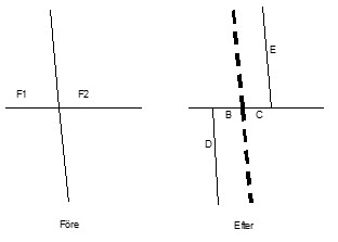
Carrying Out a Correction
A correction is made to the existing intersecting reference line’s geometry, which is the north-south direction in the image. This involves one of the following approaches:
Conditions: A change has been made to a road section, e.g., reconstruction of the road’s alignment, introduction of interchanges and roundabouts, conversion to median barriers, conversion to dual carriageways, etc.
Requirements: The history in IRDB must be maintained, i.e., it should be possible to see how the road network and its features looked both before and after the change.
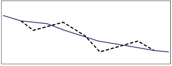
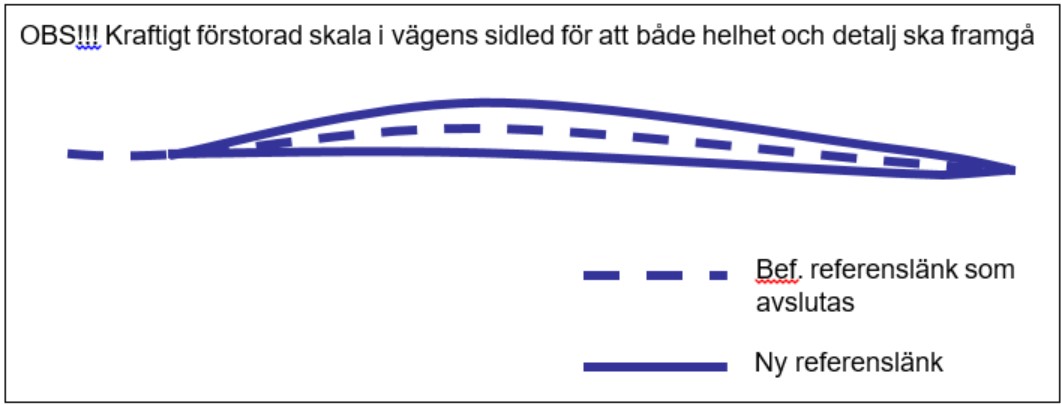
Example: The road has been reconstructed, and a curve has been straightened out. The figures below show how the road looked before the reconstruction and how it turned out afterward. In such a road section change, both the situation before and after the reconstruction are saved in IRDB’s database.


A–B is a part of the original reference link.
B–C (dashed) is the concluded part of the original reference link.
C–D is a part of the original reference link.
B–C (bold) is the new reference link.
NOTE: The new reference link must NOT start at A and extend all the way to D! The original reference link must remain and function on the stretches A–B and C–D as before.
Solution:

Add the roundabout’s reference links (the circle in the figure above). Connect it to the existing (previous) IRDB road. Conclude the previous road on the sections that are no longer in traffic, such as the parts that went through the newly constructed roundabout (the dashed parts in the figure above).
If the existing carriageway remains in the same place as before, existing reference links are retained along that carriageway, and new reference links are added for the new carriageway. Often, the reference line needs to be moved, and then new reference links must be added in both directions; otherwise, the history becomes misleading. In extensive reconstructions involving two completely new carriageways, the old reference link is concluded, and new reference links are added for both carriageways.
Apply the features that must be registered simultaneously with the road network on the newly introduced sections. Some of these features may be taken from the old road section, but many must be collected anew. Delivery must be made for all the features for which the supplier is responsible.
Rules: The action is carried out as a change. Existing IRDB reference links must not be corrected but should remain in their position. Instead, they should be concluded on the affected parts.
If the above rules are violated, the historical data will be destroyed!
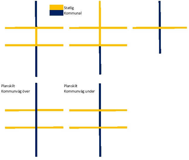
Let's take the case of an intersection between State Road with Dual Carriageway and Municipal Road with Single Carriageway as shown here:
Figure 87 shows an example of intersections between state and municipal roads, indicating the responsible road authority in the intersection.
If the short link (the one shown as red-dashed in the figure below) is completely missing in IRDB and is not entered by the municipality, National Road Administration should enter the link. Figure 88 shows the connection between carriageways.
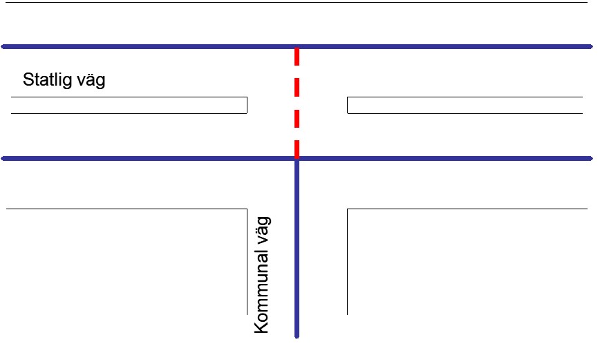
The responsibility for delivering features to IRDB on the short link between the carriageways is described by the following rules:
Road Authority
Normally, National Road Administration is the road authority for the state road (although the municipality may be the road authority for some parts within urban areas). The road authority refers to areas rather than sections generalized into one-dimensional links. In the example above, it is common for the authority responsible for both carriageways to also be the authority for the shaded area in the figure below.
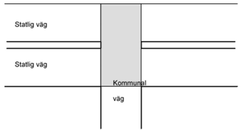
If National Road Administration is the road authority for the larger road with dual carriageways, then it is reasonable for the short intermediate link to be marked by National Road Administration in IRDB as Road Authority = State, even if the link symbolizes part of the connecting municipal road. The main reason is that if the small link is short, then the area where it is located is likely part of the larger road with dual carriageways.
Road Number
The short intermediate link should be marked with Road Authority = State, and it should also be assigned a road number (the same as the state road). This is done so that the link’s role becomes a branch.
Street Name and Other Road Name
If the municipal road has a street name, then it is up to the municipality to decide if the small intermediate link is part of the street name or if the street name begins at the next link. If the municipal road continues on the other side, the street name should be continuous through the intersection. The same rules apply to Other Road Names.
Surface Layer and Road Width
Delivered by the road authority for the short intermediate link. The link, or rather the road corresponding to the link, is in a sense fictitious if it is very short. If the width is unknown, the same width as the connecting road can be used.
Functional Road Class
Delivered by the road authority for the short link. Normally, the functional road class is set to the same class as the connecting municipal road, but if it is a branch of a state road, one can choose to set a class lower than the state main road.
Traffic Regulations
Delivered by the decision-making authority through the Transport Agency. These features are therefore completely independent of who the road authority is. If traffic regulations are missing for the short link, a deviation report should be sent to the Transport Agency.
Even in a roundabout that is an intersection between a state and municipal road, certain boundary issues arise.
Road Network Deliveries
If the municipality has a good base for the location, the municipality delivers the geometry of both roads, including the roundabout. However, coordination between the municipality and National Road Administration must always take place as usual! If there are design documents, the geometry is delivered by the party holding these documents.
Feature Deliveries
For features, it can be more challenging to determine who should deliver them. First, determine who the road authority is. Clue: National Road Administration or the municipality is usually the road authority for the roundabout.
Road Authority
Determined as mentioned above. The road authority delivers the Road Authority feature.
Road Number
Always delivered by National Road Administration. Note that some of the links in the roundabout are part of the road number’s extent.
Functional Road Class
Delivered by the road authority for the roundabout.
Street Name and Other Road Name
Street names are delivered by the municipality. If the municipal road begins or ends in the roundabout, the municipality decides whether the links in the roundabout are part of the street name. The same rules apply to Other Road Names.
Surface Layer and Road Width
Delivered by the road authority.
Traffic Regulations
Delivered by the decision-making authority through the Transport Agency. These features are therefore completely independent of who the road authority is.
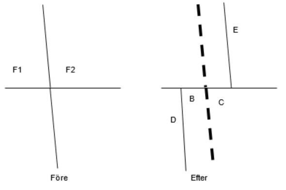
If reconstructing or generalizing a four-way intersection from or to a shifted four-way intersection, the following measures must be taken (we are talking about small shifts of approximately 10 meters). All features that exist or should exist on the short “intermediate link” must be updated so that their extents are correct. This applies to features that may be changed due to the intersection’s design, such as road number, street name, and road width, see the table below. The problem can also arise in other contexts of road network editing. If it is not easy to find out the actual situation, the update is done schematically as follows:
Review the features on Link A in the figure below as follows:
| Feature | Handling Rule |
|---|---|
| Road Administrator | The feature F1 is also applied to section B. The feature F2 is also applied to section C. |
| Recommended Road for Dangerous Goods | |
| Functional Road Class | |
| Street Name and Other Road Name |
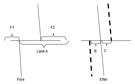
Review the features to be placed on segments B and C in the figure below as follows:
| Feature | Handling Rule |
|---|---|
| Road Administrator | If F1 and F2 are the same, apply the same feature to sections B and C. Otherwise, adjust the road administrator for F1 and F2 to apply from the four-way intersection. |
| Road Number | The road number must be repaired (note that road numbers can only be handled by the National Road Administration). This applies to both the unaltered road and the road that is now shifted. |
| Functional Road Class | Check the functional road class for all sections in the intersection. If B and C connect the two roads with the highest road class, apply the same road class to B and C. If B and C lie outside the sections with the highest classes, choose "the highest of the lowest" classes. |
| Street Name and Other Road Name | In cases where it is not clear, consult the road administrator for a decision. |
Conditions: A change has occurred in a road segment, such as road realignment, the introduction of traffic junctions and roundabouts, the addition of median barriers, or the construction of dual carriageways. After the change in an IRDB-adjusted system, several existing connecting roads may hang loose, meaning they are not connected.
Requirement: A connection of the existing connecting roads must be made (otherwise, it will not be possible to plan the road network for routing, for example).
Solution: Obtain the necessary documentation to make any changes to the connecting roads as well. The basic rule is that the stakeholder who carried out the reconstruction (usually the National Road Administration or a municipality) and who has access to design documents should also implement the change in IRDB.
Make changes to the connecting roads.
Ensure that the connecting roads are connected!
Add the features that must be registered simultaneously with the road network (features that must not be missing from a road segment, on the newly added stretches). Some of these may be taken from the old road segment, but many must be newly collected. The delivery must contain all the features for which you, as the supplier, are responsible.
Figure 92 shows the connection of a connecting road during reconstruction.
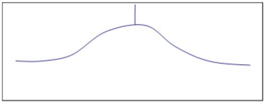
In the figure above, you can see how it looked before reconstruction: A curve with a connecting road in the middle coming from the north.
Figure 93 shows the connection of a connecting road during reconstruction.
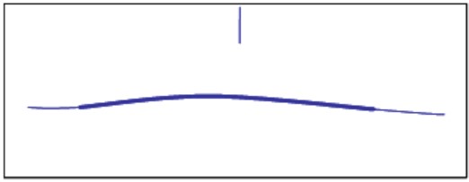
After the reconstruction: The curve has been straightened, a new reference link has been added (the heavily marked one), and the curve section has been closed. The old connecting road is “hanging in the air,” it has not been connected.
Figure 94 shows the connection of a connecting road during reconstruction.
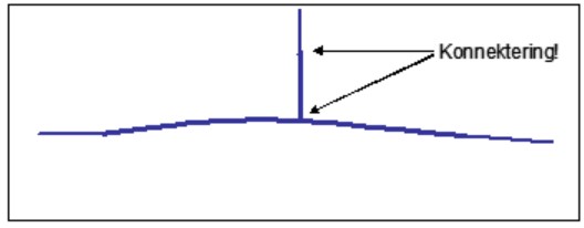
Here, a new reference link has been created in the gap for the connecting road, and the connection of the small “stump” has been made at both ends. Do not pull down (correct) the old connecting road to the new road as the history would be destroyed.
Rules:
For all reference lines, origin history must be recorded. This means that origin history must exist for how the data of the reference line was captured and possibly processed. This is done by linking all reference lines to an origin feature - Reference Line Origin. One and the same origin feature can be linked to several different reference lines, meaning that several reference lines can share the same origin history. The origin history is described partly by the method of the reference line.
The purpose of describing the origin history is primarily to make the data traceable, meaning marking it so that in the case of deviation management, the source can be identified.
For further details, refer to the data product specification – Reference Line Origin.
Add links here